

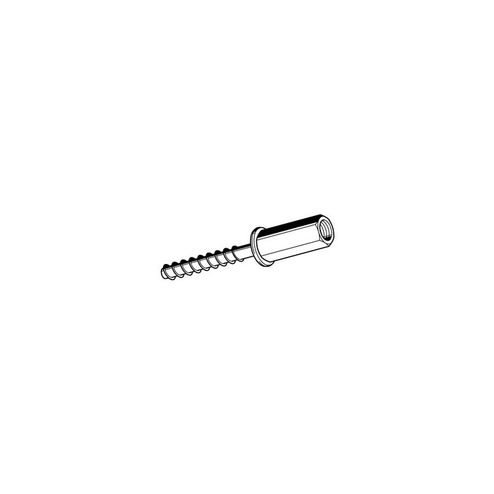
Application
Suitable for quick and safe fixation of e.g. channels and pipes to concrete and masonry ceilings or walls. To be applied in dry rooms not exposed to high corrosion resistance requirements.
- Easy installation via self-cutting action of screwbolt threads into concrete
- Small edge and axial distances to adjacent fixings, due to low expansion pressure when installed
- Also fixes into pressure-resistant natural stones and different solid bricks (not part of ETA approval / guideline)
- Flexible use for high or standard load performances due to 2 anchoring depths
- For single fixings it is possible to additionally seal the drill hole with a special injecton resin against water ingress, prior to the fixing being installed and before the injection resin sets.
Perm. loads under stress of fire in cracked/non-cracked concrete C20/25 to C50/60
| Anchoring depth 55 mm | Anchoring depth 40 mm | |
|---|---|---|
| Perm. tensile load R30 perm. F [kN] | 0.9 | 0.5 |
| Perm. tensile load R60 perm. F [kN] | 0.8 | 0.5 |
| Perm. tensile load R90 perm. F [kN] | 0.6 | 0.5 |
| Perm. tensile load R120 perm. F [kN] | 0.4 | 0.4 |
| Charact. centre distanceo scr,fi | 176 | 124 |
| Charact. edge distance ccr,fi | 88 | 62 |
Multiple fixing:
Extract from application conditions of ETA-16/0656
For multiple mounting solutions of non-load-bearing systems acc. ETAG 001, part 6.
Safety factor acc. ETAG 001 is included ( YM YF ).
The perm. loads per fixing point for the respective countries are regulated in ETAG 001, part 6.
|
Anchoring depth [55mm] |
Anchoring depth [35mm] |
|
| Drive | SW13 | SW13 |
| Nominal diameter of drill d0 [mm] | 6 | 6 |
| Depth of bore hole h1 [mm] | 60 | 40 |
|
Perm. tensile load in cracked concrete |
||
| C20/25 [kN] | 3.6 | 0.6 |
| C25/30 [kN] | 3.9 | 0.7 |
| C30/37 [kN] | 4.3 | 0.7 |
| C40/50 [kN] | 5.1 | 0.8 |
| C50/60 [kN] | 5.5 | 0.9 |
|
Perm. tensile load in non-cracked concrete |
||
| C20/25 [kN] | 3.6 | 0.6 |
| C25/30 [kN] | 3.9 | 0.7 |
| C30/37 [kN] | 4.3 | 0.7 |
| C40/50 [kN] | 5.1 | 0.8 |
| C50/60 [kN] | 5.5 | 0.9 |
| Min. thickness of component hmin [mm] | 100 | 80 |
| Charact. centre distance scr,N | 132 | 81 |
| Charact. edge distance ccr,N | 66 | 40.5 |
| Min. centre distance smin [mm] | 40 | 40 |
| Min. edge distance cmin [mm] | 40 | 40 |
| Clearance hole in component ≤ [mm] | 8 | 8 |
| Recommended max. torque Tinst [Nm] | 10 | 10 |
Perm. loads under stress of fire in cracked/non-cracked concrete C20/25 to C50/60
| Anchoring depth 55 mm |
Anchoring depth 35 mm |
|
| Perm. tensile load R30 perm F [kN] | 0.9 | 0.38 |
| Perm. tensile load R60 perm. F [kN] | 0.8 | 0.38 |
| Perm. tensile load R90 perm. F [kN] | 0.6 | 0.38 |
| Perm. tensile load R120 F [kN] | 0.4 | 0.30 |
| Charact. centre distance scr,fi | 176 | 108 |
| Charact. edge distance ccr,fi | 88 | 54 |
Prestressed concrete hollow plate ceilings C30/37 to C50/60
| Anchoring depth hnom [mm] | ≥ 35 | ||
| Nominal diameter of drill d0 [mm] | 6 | ||
| Depth of bore hole h1 [mm] | 40 | ||
| Recommended max. torque Tinst [Nm] | 10 | ||
| Level size db [mm] | ≥ 25 | ≥ 30 | ≥ 35 |
| Perm. tensile load [kN] | 0.4 | 0.8 | 1.2 |
| Min. centre distance smin [mm] | 100 | 100 | 100 |
| Min. edge distance cmin [mm] | 100 | 100 | 100 |
For calculation the whole approval is to be respected.
Material:
Steel, electro-galvanised verzinkt
Approvals
Approvals ETA-16/0655 and ETA-16/0656.
 = Sold by pack
-
-
6×35 K*
- 0.04
- 50
- 115028
- Registrati
-
-
-
- 0.04
- 50
- 115721
- Registrati
-

